|
|

I just moved the web site to a new server.
If you have any problems with pages or downloads,
let me know, Fly safe, Waiter
1 November - Fixed a couple bugs in Waiters Flight Recorder.
Found two minor problems with the recorder.
1) it wouldn't let you change folders for writing your data.
2) The
Grand Rapids OAT data wasn't decoding correctly.
A couple minor fixes, now you can
specify any drive and folder to write your files to. A phone call to Grand Rapids and they
gave the correct coding scheme for the OAT data. If you experience any
problems, or have a wish list, please send me an e-mail. Waiter
29 OCTOBER - Strong Pitch Trim System (Continued)
Here's where I'm at so far. The turning bellcrank is installed, and everything is bolted together. (NON flight
hardware at this point). The geometry of the pushrods and bellcrank is symmetrical,
so the Strong Pitch Trim Actuator should behave in this location, as it would if it
were connected directly to the control stick on the other side of the fuselage.
The canards PTB was originally used for the manual trim system. Springs and cables were attached to the upper and
lower holes on the PTB.With the Strong Pitch Trim system, I use the lower
hole. The upper hole is not used. (you can see the upper hole in photo 4).


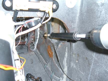
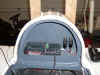
1) Viewed from the left leg hole,
looking up and forward. Transponder Tray is at the very top right, the white
areas behind the tray is the bottom of the canard. You can see how the pushrod
attaches to the Pitch Trim Bellcrank (PTB) on the canard. Note also the Strong Pitch Trim actuator as it goes just below F22.
2) Viewed from the Nose gear
actuator, looking right and aft. Note the canard mounting tab in the upper right
corner. You can see the Strong Pitch Trim actuator clearance of F22, and the
connection to the Turning Bellcrank (TUB).
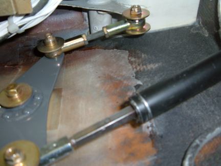
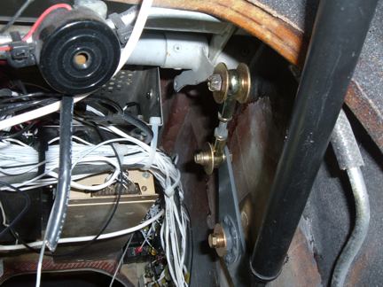
3) Viewed from below the TUB,
looking up (forward is on the right). The Pushrod that attaches to the PTB is
reasonably parallel to the Strong Pitch Trim actuator, and the rod is close to 90
degrees orientation off the PTBs turning radius. This geometry should provide linear
trim response similar to what would be seen if the actuator was mounted on the
main control rod on the right side.
4) Viewed from the left rudder
peddle, looking up and aft. Keep in mind that this is not flight hardware. Note
the pushrod is mounted on the outboard side of the canard PTB (right of the PTB),
but is mounted on the inboard side of the TUB (left side of TUB).
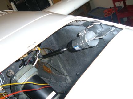
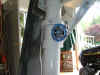
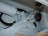
5) Viewed looking down through my
nose access cover. This gives a good idea of how the Strong Pitch Trim actuator is
oriented in the nose.I need to adjust the canard elevators to their neutral
position, then adjust the Strong Pitch Trim actuator to its neutral position, then
I'll know exactly where to install the permanent mount for the motor end of the
actuator.
26 OCTOBER - Strong Pitch Trim System

CHANGE NOTE - The orientation of
the bellcrank is changed from these photos. The Bellcrank is shaped like an
Arrow pointing forward. The new position has the arrow pointing backward, and
the top pushrod has been shortened by 1 inch.
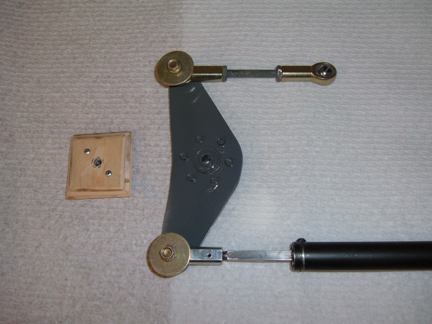
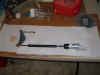
1) These are the components. This
assembly is mounted on the left side of the fuselage, with the Strong Pitch Trim servo
routed under F22 and the motor portion (silver in color) will be about 6 inches
in front of, and about 3 inches above the left rudder pedal. The rod at the top
of the photo attaches to the lower hole of the existing PTB bellcrank that's on
the left side of the canard.The pitch trim springs used to attach to the
PTB, one on top and one on the bottom.
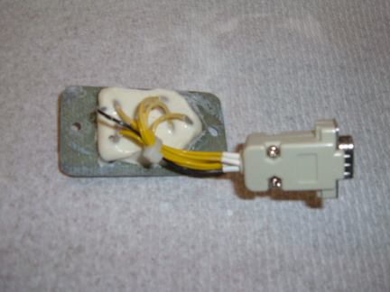
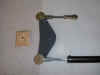
2) The wooden hardpoint is made of
1/4 aviation plywood with a K1000-4 nutplate riveted on the back. Look very
carefully at the shape of the new bellcrank, now get your drawings out and look
at the lower part of the Landing brake bellcrank. I happened to have a landing
brake bellcrank, so I cut the handle off and made the upper and lower parts symmetrical.
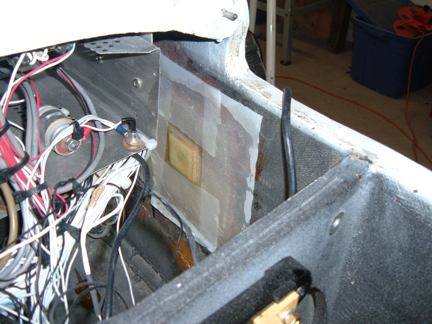
3) the new hardpoint is embedded on
the left side of the fuselage with three layers of BID to secure it in place.
23 OCTOBER - More Electrical
Most of the weekend was spent wrapping up some small details of the new LongEZ electrical system.
Ken Millers Speed Brake actuator is wired up
and tested. Normal Speed brake operation is accomplished via a thumb switch on
the Infinity Aerospace Stick Grip. The Landing gear computer interface that automatically
retracts the speed brake is now hooked up and works correctly. The Landing Gear
computer forces the speed brake to retract anytime the throttle is placed in a
full position. It also forces a retract if the EMERGENCY RETRACT switch in
placed in the RETRACT position.
The Pitch Trim actuator was wired
and check for operation. The Strong Pitch Trim is an actuator that's also
controlled by the Coolie hat switch on the Infinity Aerospace Stick Grip.
One of the puzzles I've been trying
to solve, is how to mechanically attach the Strong Pitch Trim actuator to the LongEZ
control system. Strong has you attach the actuator to the control rod that's
driven by the control stick. This would probably work OK, but I have two
thoughts on this; 1) Its very crowded on the right side where the actuator would
be mounted, and 2) I would be giving up the "redundant" flight control
feature of the manual pitch trim system.
The Manual Pitch trim system uses
spring loaded cables that attach to the canard on the left side. I like this
because it offers a redundant flight control path in the very unlikely event
that the main pitch control became disconnected.
The software for the landing gear
computer looks good. I was able to to simulate most problems I could think of,
and the computer handled them correctly. I'm not ready to put hydraulic fluid in
the system yet, but I'm getting anxious to do a full retract.

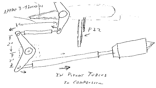
1) Sketch of how the Strong Pitch Trim
actuator will mount on the left side, A hard point will be installed on the
inside of the fuselage to bolt the bell crank to. The pitch trim bell crank is actually
made by cutting off the unused Landing Brake manual bell crank. An actuator arm approximately
3 inches long will attach to the lower hole on the existing PTB fitting on the
canard. The other end of the arm will attach to the top of the newly installed
bell crank on the fuselage. The Strong Pitch Trim Trim servo will attach to the
bottom of the bell crank.
This technique operates in
compression, that is, as flight loads are placed on the canard and the
elevators, it will compress the Strong servo. If the servo was installed per
plans on the right side, flight loads would be in torsion on the Strong servo.
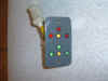
2 & 3) My original gear status
indicator, I placed the RED UP leds on the bottom. WRONG.I switched the
RED and GREEN so they are now more ergonomically correct. The LED to wire
connections are fragile. To reduce problems associated with vibration, I encased
the backside of the LEDs in micro. I made a small batch of epoxy and mixed in
just a little micro to thicken it a little.
20 OCTOBER - The Need for Speed
I need UPLINK speed
from my WebCam to your Computer. Until my ISP, MetaLink, does something about it, I'm
afraid the WebCam connectivity will suffer. I've added a "SNAPSHOT" to
at least show you something from the shop WebCam. The snap shot gets updated
every 90 seconds if the WebCam "see's" any movement in the shop
.
UPDATE - I may have
stumbled on the reason for low UPLINK speed. I installed a 10db gain amplifier
in the rf cable, and this seems to have helped significantly. I'll call the
Provider on Monday and see if they can send a service person out to completely
redo the RF path (cable and antenna). I'm keeping my fingers crossed.
16 OCTOBER - Gear Control Computer and interface
I spent most of the weekend routing
wires to and from the computer. The Control computer is an industrial PLC (Programmable
Logic Controller) identical to units found on factory floors throughout the world.
All of the wiring is now connected
to the computer and I've begun performing initial testing/debugging of the
computer software against "Real Hardware". I found a couple minor bugs and have them corrected. I also
have updated the design document and the electrical diagrams to reflect the
latest changes. I have one sequence approach for controlling the main gear
that I'm not happy with, so I'll be rewriting that portion of the code over the
next couple days.
If your interested in how this thing
works, your welcome to download my
design interface document and review it. Although this document is
constantly being updated, its fairly close to a finished product. ALSO, if you
see something that your not sure about, drop me an e-mail, its quite possible
I've overlooked something in my design.
With the PLC installed, I'm now able to
power up and run the controller in the plane. Some of the modes being tested
are:
Safe boot mode - This doesn't allow
the computer to boot up unless cockpit switches are in a known safe mode for startup,
i.e., if the main switch is in the RETRACT position, then the gear must be fully
retract with all the retract parameters correct (canopy closed, airspeed above
60kts, etc) or the computer stops until the cockpit switches are placed in a
safe mode. ( An EC-135 I flew back in the 70s had the nose gear retract when
someone left the gear handle in the UP position after maintenance, I bet they
wish they had a system like this back then.) Basically, the system reconciles
the UP/OFF/DOWN switch, the EMERGENCY RETRACT switch, and the ALARM MUTE switch.
Input Self Test - a mode that
displays the status of all the switches and sensors.
Output Self test - a mode that
sequences all the relays, solenoids, indicators, etc.
Normal Retract and Extend - Although
I'm not
able to run the main gear yet (no hydraulic fluid), I use software "forces"
to
simulate some of the main gear sensors, and can watch how the program reacts to
different switch positions. The Nose gear portion is fully installed and functional.
I've been able to perform normal and emergency operations with the nose gear flawlessly.
EMERGENCY RETRACT Mode - This mode
overrides all safety's and performs a normal retract of all gear, works OK.
DEAD COMPUTER MODE - This is a
hard-wired override that allows the mains and nose gear, plus the main gear struts, to be extended electrically,
without
the computer. This is an emergency mode that has no safeguards.
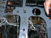
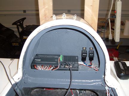
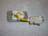
1) Gear computer is located in the
rear headrest area. The small cable coming out is used for programming the PLC.
The two relays to the right are the Strut relay, and the Landing Light Enable
relay.
The Strut relay controls a solenoid
valve the directs pump pressure to either compress or extend the main gear
struts.
The Landing lights are located on
the main gear struts, I don't want them to accidentally be left on while the
gear is retracted, so this relay shuts power off to the landing lights (if
they're turned on) when the gear is NOT extended.
Most of the other control relays are
located in the nose.
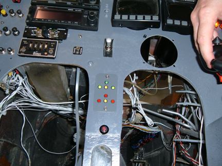
2) The gear status lights are shown
in the center of the photo. I'm going to redo these. I need to reverse them so
the RED "UP" lights are on the TOP, and the GREEN "down" lights need to be on the bottom. I once owned a
Mooney, when the handle was UP, the gear was DOWN, and when the handle was DOWN,
the gear was UP. I HATE BACKWARD STUFF!
2 OCTOBER - Gear Leg Wiring
Spent most of the day fishing wires
into both wheel wells. I first drilled my access hole on the ends of the
centerspar (CS). I used a fish tape to pull a wire from the back seat thru the
CS. I then reached through the small hole in the wheel well with a clothes
hanger hook, and snagged the wire. Each wire set was then twisted with a
ground wire, and the wires were then pulled through the CS into the well.
1) These are the landing lights,
55watt, one on each gear leg.
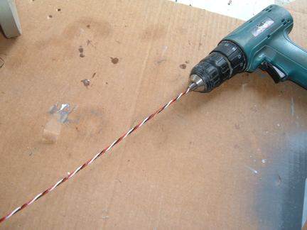
2) How to make twisted wire. Secure
one end to something solid, then place the other ends in a drill chuck, and
crank it up. I used the wire marker to label the wires before I twisted
them.
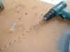
3) Right gear well wiring complete.
You can make out the UP switch at the top right of the photo, The Centroid Fuel Probe sender is at the three oclock position. The magnetic DOWN switch can be
seen (wires) lower left.
28 SEPTEMBER - INTERNET and CAMERA CONNECTIVITY
I'm just about physically recovered
from Harvest, so I've been doing some jobs around the house that have been neglected
for the past couple months.
I had some network problems at my
house during harvest, so I just patched around just to keep the servers up. I
reloaded the Linux firewall and had to purchase a new wireless bridge (I live
out in the sticks, so I have a high speed wireless connection to my ISP ).
I think I found the reason why my
network camera would occasionally lock up my FTP server, so I updated the
NetToWeb software, Hopefully it won't lock up my FTP server anymore. I may
release this software to the public if it looks like its going to be
stable.
Speaking of Flights, Tony
Kirk, one of our local RV builders recently conducted his first flight (congratulations
Tony). Tony was very pleased with the performance of my recorder
software. He was able to record his Dynon EFIS,
Grand Rapids Engine
Monitor, and a GPS signal. Look under Waiters
Flight Recorder. This is FREE and will definitely be of help when performing
any test flights.
25 SEPTEMBER - HARVEST IS OVER
We had a very good harvest this
year. Productivity was up 25%, with automation playing a significant part in
this increase. The crop was very good, and most important, we had no job related
injuries during the "Pack" . OK, Now its time to get back
to work on airplanes. Waiter
Waiters GPS Set Time program.
Waiters Flight Data Recorder.
Flight Data Recorder.
Recording aircraft flight data.
Aircraft Voice recorder.
Garmin GPS.
Garmin GPS Serial data Format.
Recording EFIS data.
Capture Serial data.
Convert Raw Data Files.
Free GPS Software.
Reading GPS data.
Reading Garmin GPS data.
Aircraft EFIS Flight Instruments.
Electronic Flight Instruments.
Aircraft Engine Monitor System.
Garmin G format.
Infinity landing gear LongEZ Plans Built Airplane.
Oil Heat system for Homebuilt airplane.
LongEZ Canard and main Wing.
Dynon instrument panel.
Custom Mouse cursors.
Garmin Serial Data Format.
Easy, Free Computer Time setting by GPS Receiver.
Custom mouse pointers.
Custom airplane mouse pointers.
LongEZ Nose gear doors.
Long-EZ main landing gear doors.
LongEZ grasscutter landing gear door.
Custom LongEZ mouse pointers.
Lycoming engine in LongEZ.
MT Propellor with 6 inch propellor extension.
EZNose Lift retractable nose gear for Long-EZ.
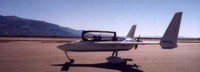
Rutan LongEZ is a plans built aircraft.
High speed homebuilt airplane.
Retractable landing gear for LongEZ.
Custom Airbus mouse cursor pointer.
Custom Velocity mouse cursor pointer.
NMEA 0183 Serial data Format.
Custom Cozy mouse cursor pointer.
Custom Aerocanard airplane mouse cursor pointer.
Custom E-Racer mouse cursor pointer.
Custom Canard airplane mouse cursor pointer.
Custom LongEZ mouse cursor pointer.
Set your Computer clock with this free GPS software.
Custom F15 mouse cursor pointer.
Custom A10 Warthog mouse cursor pointer.
LongEZ Hydraulic pump.
Retractable landing gear for a Long-EZ.
Custom F16 mouse cursor pointer.
Custom F14 mouse cursor pointer.
Custom Boeing 747 mouse cursor pointer.
Custom Boeing 767 mouse cursor pointer.
Custom Boeing 777 mouse cursor pointer.
Custom Boeing 737 mouse cursor pointer.
GPS Time Sync.
Custom Boeing 727 mouse cursor pointer.
Landing gear door rigging.
Custom Boeing 757 mouse cursor pointer.
Custom MD80 mouse cursor pointer.
Custom DC9 mouse cursor pointer.
Setting your computer to a GPS Time.
Custom RV mouse cursor pointer.
Downdraft cooling for LongEZ.
Speed brake installation.
Waiters Flight Data Recorder.
LongEZ Baggage pods installation instructions.
Waiters Custom Airplane mouse cursors.
Free GPS Time Sync Program.
LongEZ Intercom installation.
Major airframe overhaul of plans built EZ.
Weight and balance for a LongEZ.
Weight and Balance spreadsheet download for a Long-EZ.
LongEZ fuel system design.
How To remove the wings from a LongEZ.
How To remove the canard from a LongEZ.
Waiters GPS Time sync program runs on PC.
How To remove the engine from a LongEZ.
Long-EZ Downdraft cooling for a Lycoming O-320.
Long-EZ Wing Removal and installation instructions.
Waiters Retractable Landing Gear Controller.
Landing Light installation in LongEZ.
Install free EFIS software on your PC.
How to Put several longezs in one hangar.
How to install an Infinity Aerospace Retractable landing gear in a Long-EZ.
How to install DownDraft cooling on a Long-EZ.
GPS Time.
Setting you computer clock to GPS time.
How to set your Computer clock to GPS Time.
Using your GPS Receiver to set your computers clock.
Low cost GPS receiver used to syncronize Computer clock to GPS time.
Neat Canopy stay system for an EZ.
Cabin Heat using engine oil as source.
Waiters GPS Time, Syncronize your PCs internal clock with the GPS satellite.
Remote display of EFIS on a PC.
Cabin Oil Heater for a LongEZ.
LongEZ Landing Gear Door.
Rigging a LongEZ Landing Gear door.
Icom Radio in LongEZ.
How to Build a Manometer.
LongEZ Electrical system upgrades.
Grand Rapids EMS.
Custom Windows cursors.
Custom Windows mouse pointers.
LongEZ Cowling for downdraft cooling.
Record holding LongEZ flights.
Using a PLC for a retractable Landing Gear Controller in a LongEZ.
Syncronize your PCs clock to a GPS receiver.
Airspeed vs pressure lookup tables.
How to build a homebuilt airplane.
Video of LongEZ taking off.
Grasscutter landing gear door.
EZ Nose Lift installation.
Landing Gear status indicator.
Shareware software can set your PC clock vie a GPS receiver.
Landing Gear controller computer for LongEZ.
Landing gear doors.
Dynon EMS10 installed in instrument panel of a LongEZ.
Dynon EFIS D10A installed in instrument panel of a LongEZ.
Flight Data Recorder Software.
PlansBuilt LongEZ.
Video of High G turn in a Long EZ.
Strong Pitch Trim system installed in a LongEZ.
Strong Pitch Trim mounted on Left Side of Long-EZ.
Free software sets your PC clock with a GPS receiver.
Video of LongEZ Taking off.
Video of LongEZ Landing.
Video of LongEZ performing a high G turn.
Video of Infinity Landing gear being retracted into a LongEZ.
LongEZ Color White.
Painting your LongEZ.
White LongEZ.
Camoflage LongEZ.
Infinity Landing Gear for LongEZ.
Strong Pitch system.
|