|
|

I just moved the web site to a new server.
If you have any problems with pages or downloads,
let me know, Fly safe, Waiter
10 AUGUST - HARVEST
I'm a program manager responsible for all the automation and process control at
four food plants scattered around Northwestern Ohio. Needless to say, when we
start harvesting (working 16 - 18 hours / day) it leaves ZERO time for
airplanes. Life isn't fair. Visit www.hirzel.com
. Things gets back to normal in 6 to 8 weeks. Waiter
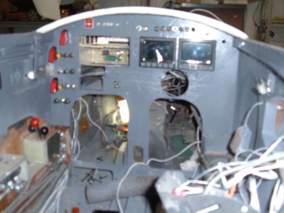
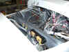
31 July 2005:Panel & Stick
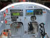

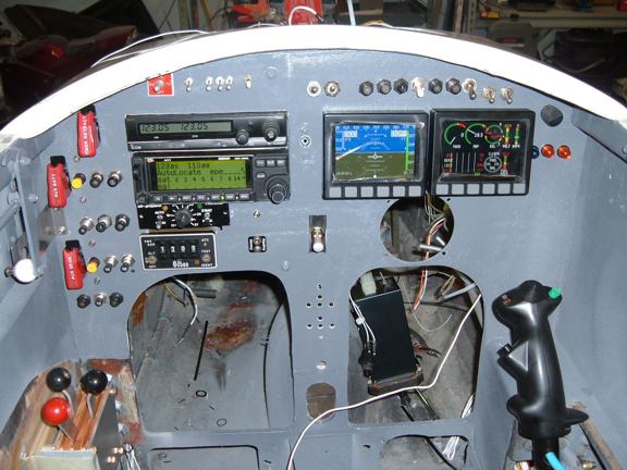
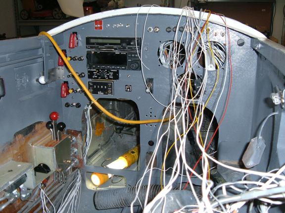
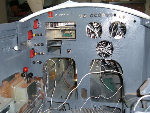
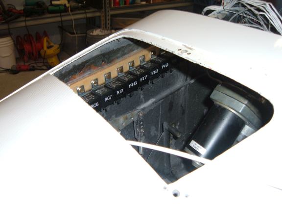
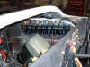
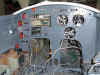
1) As you can see, electrical things are now working again. Both Comms are OK,
Intercom OK, The Dynon EFIS powers up and works OK. I used it testing my
EFIS Recorder software. The Dynon EMS powered up and is transmitting serial
data. I'll start hooking up some of the sensors this week.The hole in the panel
is for the NavAids Autopilot. The power runs to it and it checked OK. I could
run the servo with the GPS coupler. I still need to label most of the circuits,
but so far everything is running OK.
The Infinity Aerospace Stick Grip is wired up and checks out OK. The Roll trim servo
moves OK, The Strong Pitch Trim trim servo isn't installed, but the control relays
energized OK. Same for Ken Millers Speed brake. Radio Key works OK, and is selectable
with the panel switch (COM! and COM2)
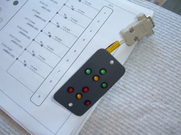
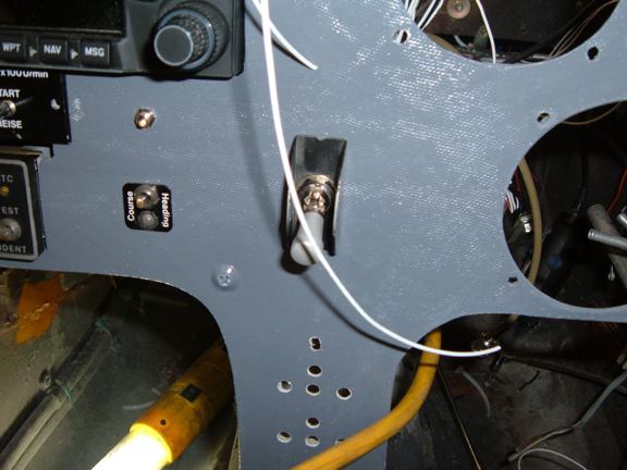
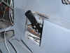
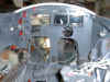
2) This is the Landing gear indicator module I built. This will also be
installed this week. It goes in the center of the instrument panel about the
same location as the manual nose gear crank used to be.
30 July 2005:FLIGHT RECORDER UPDATED.
The latest version of the Flight Recorder (2.1.1) also allows the recording of
the Dynon EMS data.
I added a separate page for the Flight recorder. Look to the left under
DOWNLOADS. Come back here on a regular basis to see what the latest version is.
If you have any ideas, recommendations, bugs, etc, send then to me and I'll see
if I can incorporate them. Thanks
Contact me at: 
25 July 2005: EFIS / GPS Flight Data Recorder.
To see what the latest version is, click on the screen shot icon and look at
the version number. The screen shot will always be the latest screen shot from
the latest version.
Here's what I've been doing when its to hot to work in the shop.
This is a neat little program for displaying and recording GPS and/or EFIS
data. The Recording time can be as fast as 63 times per second (if Dynon EFIS
10 or 10A is installed), or you can slow it down to one entry every 30 seconds.
The Data file is stored as a Tab delimited Text file, that can easily be loaded
into any spreadsheet program.
23 July 2005: Infinity Aerospace Stick Grip.
One of the problems associated with aircraft systems, where/how do you provide
the Pilot with a safe and reliable way of controlling the various systems
(operator interface) If your systems are controlled by electricity, as mine
are, then JD from Infinity
Aerospace has a realistic solution to the interface problem. The
Infinity I Military Style Stick Grip.
Rather than mount toggle switches on the instrument panel or on the armrest,
the Infinity Aerospace I Military Style Stick Grip places controls right at the pilots
fingertips.
Each stick is custom configured as to what each switch does, and how it
behaves. i.e. is the switch normally open, or normally closed, also, is it a
momentary contact or a push on / push off style.

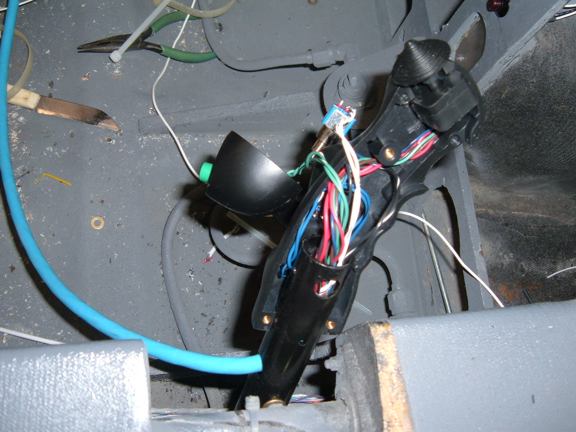
1) I had to disassemble the grip in order to mount in on my stick. I was very
impressed to find good quality switches being used throughout. I also like the
thickness of the molded parts and the way things are held together, This isn't
some piece of cheep junk, but very good quality design and workmanship.
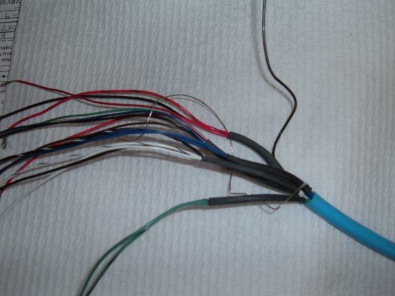
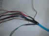
2) The stick comes with a prewired pigtail of any length you specify. If you
don't specify, you get a 3 ft piece. I SCREWED UP, I should have ordered the
Grip with an 8 foot pigtail, then I wouldn't be splicing wires (URGH).
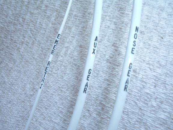
To make my life easier, I opened the wire bundle and separated the wires for
each switch into their appropriate groups, then put a piece of shrink tubing on
the group. This is important to make sure I get the correct wires for each
switch, i.e. there are several black wires in the bundle, but they each connect
to their own switch, same for a couple red wires. Use an ohm meter to make sure
you have the right wires for the corresponding switch. I also went as far as to
make an assignment sheet for the stick. This sheet is part of my wire diagram
bundle. WIRING DIAGRAMS
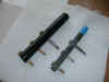

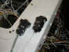
3) One of the recommendation that JD makes for us LongEZ types, is to replace
the original stick with a one inch diameter stick. The 1 inch is on the left,
and the original is on the right. The blue tape on the original marks where the
original grip bottom is positioned. The Infinity Aerospace grip will be in exactly the
same position.
I wasn't going to do this originally, and had even ordered an adapter from JD.
HOWEVER, When I started looking on how I was going to feed the wire bungle
around the adapters, I just didn't like it. SO, A scrounge through the scrap
pile to find a one inch tube.
4) The way the tube is mounted, it won't effect the controls or clearances. It
effectively moves the grip inboard approximately 1/4 inch, thus provide an
additional 1/4 inch of clearance between the grip, and the stick/hand
indentation that is built into the right fuselage.
5) Not a pretty site (yet) but this gives an idea how the wire bundle is now
routed through the stick and out the aft side of the stick.
17 July 2005: Electrical, Throttle Switches.

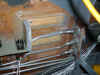
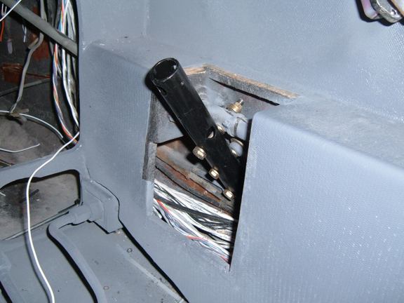
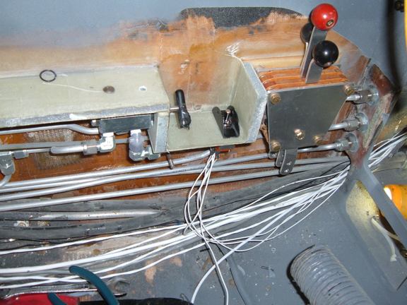
1) This is a standard Aircraft Spruce throttle assembly, with a few modifications. I cut
the left outside control arm and re-bent it so it is a mirror of the right
outside control arm, as far a height shape, etc. The left arm is Carb Heat, The
middle is Throttle, and the right is mixture.
I also added two micro switches, one for full throttle, and one for idle
throttle.
I also replaced the nut on the pivot bolt with a nut plate. This will allow me
to adjust the throttle friction to suit my needs, without having to get a
wrench on the pivot nut.
2) The mounting plates for the throttle (and many other items) is made out of
1/4 aviation plywood. I then riveted a nut plate to the back of the plywood.
Mount the plywood to the airframe with flox, then put one layer of BID all the
way around.
NOTE: the switch to the left is my AUX GEAR / STRUT bypass. This will allow me
to lower the gear and / or extend the strut in the event of a computer failure.
(Another backup to the backup)
10 July 2005: Electrical, Continued.
Almost all of the cockpit area is now complete. Radios, autopilot, Landing Gear
relays, aux landing gear control, etc.


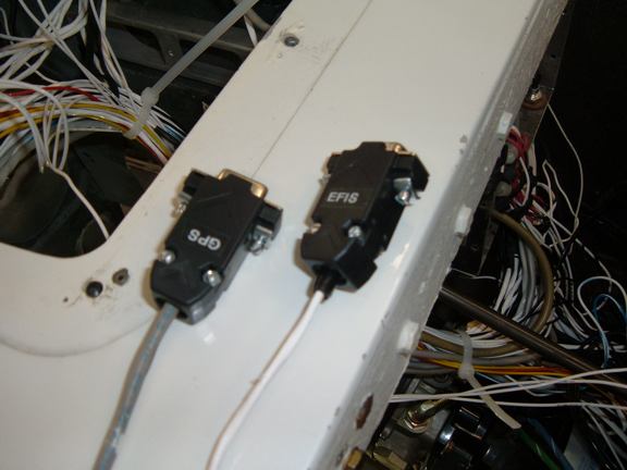
1) Serial connectors for the Garmin 250XL and the Dynon EFIS.
This is GPS NEMA 0183 data. The Navaids autopilot doesn't use this, it uses the
Garmin AP+ and AP- voltage.
The Dynon EFIS outputs a serial stream containing airspeed, altitude, and three
dimensional accelerometer data. The data is coming out fast (115,000 bps) and
updates 20 times a second. This will overwhelm almost any terminal program.When
I get caught up with other tasks, I'll write a program that will allow me to
parse the data and record it to the hard drive every second or so.
2) Wires strung, Having the label machine makes life EZ. Each wire has its own
label, and its imprinted about every 18 inches, so finding wires is real EZ.
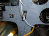
3) This is the AUX Gear control switch This is a momentary contact with the
center OFF. This switch ties directly to the main and nose gear, and the main
STRUT extension solenoid. When moved to the right, the MAIN and NOSE gear
solenoids are energized, and these gear will lower. When moved to the left,
this energizes the STRUT solenoid and extends the main struts. NOTE - The AUX
POWER switch (covered on the main panel) must be ON, and the main gear switch
must be in the DOWN position for the AUX switch to work.
The Micro switches for the Throttle FULL and CLOSED need to be wired yet.
4) The MAIN GEAR switch, This is a pull to unlock switch, with the center being
OFF.
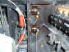
5) View of the relays and solenoids for control.
6) view of the ammeter shunt and the connections for the Hydraulic pump.
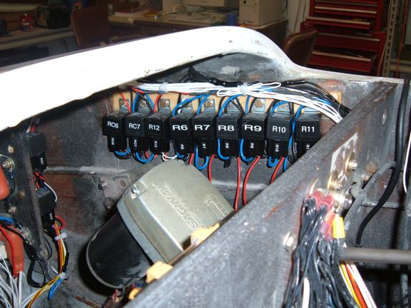
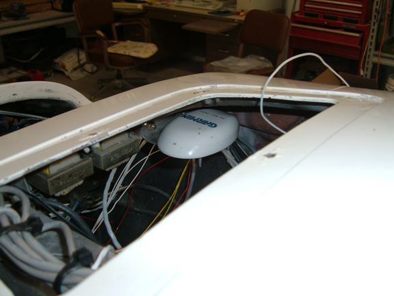
8 July 2005: Electrical, Continued.
Spent most of the week installing and testing the electrical system. These
include the relays (14 in all) used throughout the plane.
1) Primary DC distribution is complete and tested. Relay s are wired with the
exception of the control circuit.
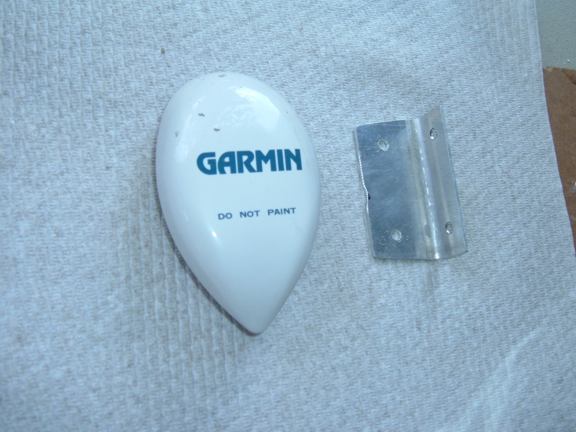
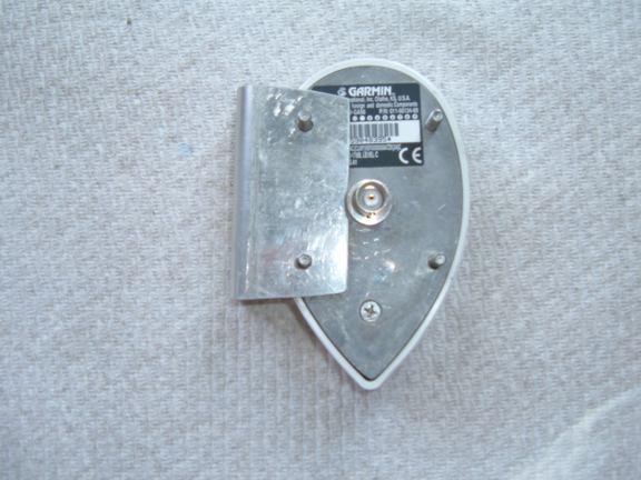
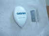
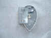
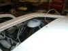
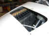
2, 3, 4) Where to hide the GPS antenna. Make a small aluminum bracket and mount
it behind F28.
6 July 2005: Intercom.
Someone expressed an interest in how I wired my radios and intercom into my
LongEZ. Basically, I purchased the least expensive intercom I could find. This
happened to be a ATC-2 Intercom battery powered, 2 place, Portable Intercom. These
intercoms are nice in that they have VOX capability, and automatically route
the MIC and KEY lines to the radio that's connected. I I have TWO Comm Radios,
so I run the radio MIC and KEY lines through a DPDT switch. There is a simple
drawing of the select switch and my intercom connections under the
UPGRADES - ELECTRICAL, Look at Page 18.

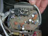
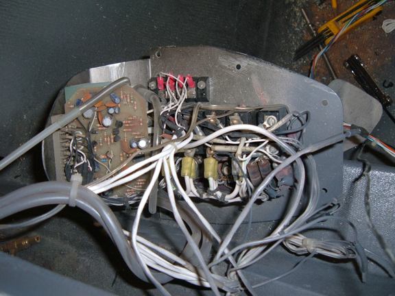
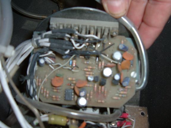
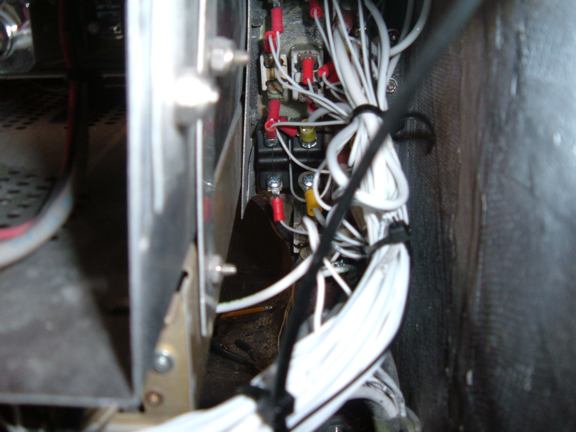
1 & 2) I took the ATC-2 Intercom apart, being very careful to document where all
the wires attached, so I could re-wire it the same way. I mounted the circuit
card to a panel, and ran all the local wires directly to the components, The
"local" wires were for, Volume control, Squelch Control, Pilot Mic
and Headset connectors, and the AUX AUDIO In and OUT jacks. I was able to reuse
the Mic and Headset audio connectors, and the original Volume and Squelch pots.
I added 1/4 inch connectors for the AUX AUDIO connectors.
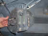
The terminal strip at the top of Photo 2 is used to connect the rear seat Mic,
Key, and Headset audio. The terminal strip also connects the Mic, Key, and
headset audio from the intercom to the radios.
NOTE: I installed a "kill" switch for the rear seat Mic and Key lines
on my main instrument panel. This allows me to override these two signals in
case I have an overly talkative passenger.
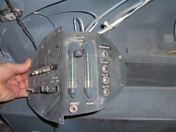
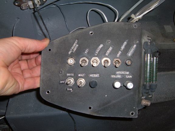
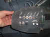
3) The Mic, Headset Audio, and the Aux Audio In and Out connectors can be seen
on the right. In the center, are two flow meters for my Built in Oxygen system
(Note the BNC connector at the bottom, is a hollowed out, This is how I connect
my mask to the O2 system, with the hollowed out BNC connector (Hey, Its a LOT
less expensive then the "official" O2 connectors.
4) You can see the original ATC-2 Intercom Volume and Squelch controls are mounted on the
lower left of the panel. Power for the Intercom is applied through a 1 amp
circuit breaker.
4 July 2005: Electrical Installation, Pump Relays.
Most of the LongEZ main power distribution is now wired. I also updated the
drawings to fix a couple errors and to implement the "As Builts"

1) Power distribution circuit breakers and switches on the left side and the
top. An up to date line drawing shows the captions, CLICK
HERE to view the drawing.
2) getting between the radios and the fuselage is tight fit.
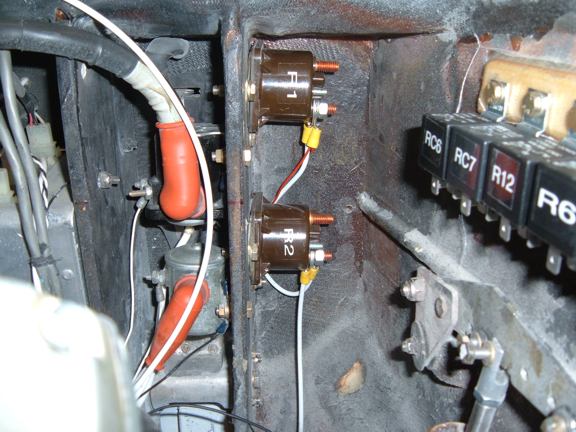
3) The two new Hydraulic pump solenoids are mounted just above the nose gear.
There are three more relays that get mounted in here.
<4) A view of the cube relay mount.
2 July 2005: Electrical Installation.
The weather has cooled down and most of the Honey Do's are complete. SO, Back
to work on the EZ.
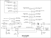

1) This is the latest electrical drawing for main power distribution. This
version incorporates a "DUAL" power source (battery) for use in the
upcoming dual electronic ignition.
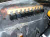
2) Our wire label machine imprints on a 20 gauge, and a couple 12 gauge wires.
This makes for finding the right wires Vari EZ.
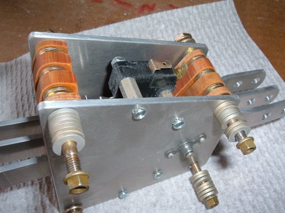
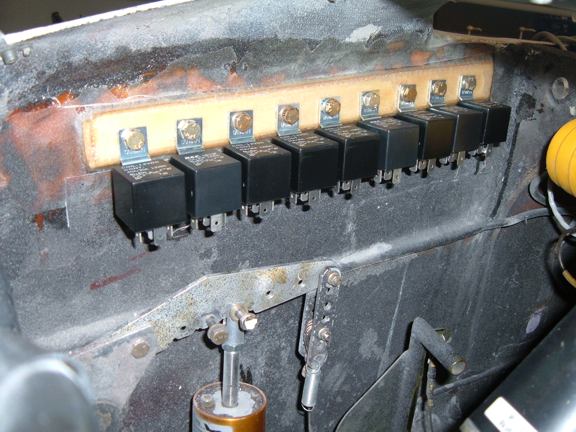
3) These are automotive relays mounted on a strip in the nose. These relays can
handle up to 30 amps. I use a lot of these Pitch / roll trim, speed brake, nose
gear, etc.
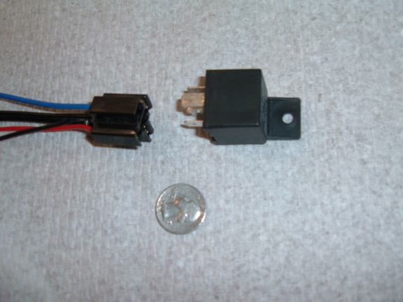
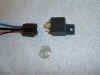
4) The relays and a pigtail (with suppression diode) are available from Jameco.
The relays are $2.49 each (part# 148582CH) and the pigtail is $2.35 (Part#
170624CH)
Waiters GPS Set Time program.
Waiters Flight Data Recorder.
Flight Data Recorder.
Recording aircraft flight data.
Aircraft Voice recorder.
Garmin GPS.
Garmin GPS Serial data Format.
Recording EFIS data.
Capture Serial data.
Convert Raw Data Files.
Free GPS Software.
Reading GPS data.
Reading Garmin GPS data.
Aircraft EFIS Flight Instruments.
Electronic Flight Instruments.
Aircraft Engine Monitor System.
Garmin G format.
Infinity landing gear LongEZ Plans Built Airplane.
Oil Heat system for Homebuilt airplane.
LongEZ Canard and main Wing.
Dynon instrument panel.
Custom Mouse cursors.
Garmin Serial Data Format.
Easy, Free Computer Time setting by GPS Receiver.
Custom mouse pointers.
Custom airplane mouse pointers.
LongEZ Nose gear doors.
Long-EZ main landing gear doors.
LongEZ grasscutter landing gear door.
Custom LongEZ mouse pointers.
Lycoming engine in LongEZ.
MT Propellor with 6 inch propellor extension.
EZNose Lift retractable nose gear for Long-EZ.
Rutan LongEZ is a plans built aircraft.
High speed homebuilt airplane.
Retractable landing gear for LongEZ.
Custom Airbus mouse cursor pointer.
Custom Velocity mouse cursor pointer.
NMEA 0183 Serial data Format.
Custom Cozy mouse cursor pointer.
Custom Aerocanard airplane mouse cursor pointer.
Custom E-Racer mouse cursor pointer.
Custom Canard airplane mouse cursor pointer.
Custom LongEZ mouse cursor pointer.
Set your Computer clock with this free GPS software.
Custom F15 mouse cursor pointer.
Custom A10 Warthog mouse cursor pointer.
LongEZ Hydraulic pump.
Retractable landing gear for a Long-EZ.
Custom F16 mouse cursor pointer.
Custom F14 mouse cursor pointer.
Custom Boeing 747 mouse cursor pointer.
Custom Boeing 767 mouse cursor pointer.
Custom Boeing 777 mouse cursor pointer.
Custom Boeing 737 mouse cursor pointer.
GPS Time Sync.
Custom Boeing 727 mouse cursor pointer.
Landing gear door rigging.
Custom Boeing 757 mouse cursor pointer.
Custom MD80 mouse cursor pointer.
Custom DC9 mouse cursor pointer.
Setting your computer to a GPS Time.
Custom RV mouse cursor pointer.
Downdraft cooling for LongEZ.
Speed brake installation.
Waiters Flight Data Recorder.
LongEZ Baggage pods installation instructions.
Waiters Custom Airplane mouse cursors.
Free GPS Time Sync Program.
LongEZ Intercom installation.
Major airframe overhaul of plans built EZ.
Weight and balance for a LongEZ.
Weight and Balance spreadsheet download for a Long-EZ.
LongEZ fuel system design.
How To remove the wings from a LongEZ.
How To remove the canard from a LongEZ.
Waiters GPS Time sync program runs on PC.
How To remove the engine from a LongEZ.
Long-EZ Downdraft cooling for a Lycoming O-320.
Long-EZ Wing Removal and installation instructions.
Waiters Retractable Landing Gear Controller.
Landing Light installation in LongEZ.
Install free EFIS software on your PC.
How to Put several longezs in one hangar.
How to install an Infinity Aerospace Retractable landing gear in a Long-EZ.
How to install DownDraft cooling on a Long-EZ.
GPS Time.
Setting you computer clock to GPS time.
How to set your Computer clock to GPS Time.
Using your GPS Receiver to set your computers clock.
Low cost GPS receiver used to syncronize Computer clock to GPS time.
Neat Canopy stay system for an EZ.
Cabin Heat using engine oil as source.
Waiters GPS Time, Syncronize your PCs internal clock with the GPS satellite.
Remote display of EFIS on a PC.
Cabin Oil Heater for a LongEZ.
LongEZ Landing Gear Door.
Rigging a LongEZ Landing Gear door.
Icom Radio in LongEZ.
How to Build a Manometer.
LongEZ Electrical system upgrades.
Grand Rapids EMS.
Custom Windows cursors.
Custom Windows mouse pointers.
LongEZ Cowling for downdraft cooling.
Record holding LongEZ flights.
Using a PLC for a retractable Landing Gear Controller in a LongEZ.
Syncronize your PCs clock to a GPS receiver.
Airspeed vs pressure lookup tables.
How to build a homebuilt airplane.
Video of LongEZ taking off.
Grasscutter landing gear door.
EZ Nose Lift installation.
Landing Gear status indicator.
Shareware software can set your PC clock vie a GPS receiver.
Landing Gear controller computer for LongEZ.
Landing gear doors.
Dynon EMS10 installed in instrument panel of a LongEZ.
Dynon EFIS D10A installed in instrument panel of a LongEZ.
Flight Data Recorder Software.
PlansBuilt LongEZ.
Video of High G turn in a Long EZ.
Strong Pitch Trim system installed in a LongEZ.
Strong Pitch Trim mounted on Left Side of Long-EZ.
Free software sets your PC clock with a GPS receiver.
Video of LongEZ Taking off.
Video of LongEZ Landing.
Video of LongEZ performing a high G turn.
Video of Infinity Landing gear being retracted into a LongEZ.
LongEZ Color White.
Painting your LongEZ.
White LongEZ.
Camoflage LongEZ.
Infinity Landing Gear for LongEZ.
Strong Pitch system.
|