|
|
Waiters Roll Trim System
Over the years I've had many requests to tell other EZ owners how I built and installed my Electric Roll Trim system. Well, here goes:
I installed this system when I originally built my EZ back in the late 80s. The system has over 2600 hours on it, with no problems.
I used one of the inexpensive MAC servos (Name change to RAC) The unit I selected has a 1 inch throw (Model T2-10A), The other models would probably work. When attached to the Aileron Torque tube with the spring/rod system, The trim has enough authority to correct for a 15 gallon difference between the Left and Right tanks.
The trim springs are loaded so they can easily be overridden if the pilot moves the control stick.
This system will require you make one part (the "X" tube needs to be welded) and you'll need to purchase a couple parts from the local hardware store (springs) and the local Hobby Store, (Nylon tube and threaded rod)
This entire text and all photos can be
DOWNLOADED and printed.
PARTS LIST
1 ea MAC S6A Servo motor (RAC = T2-10A)
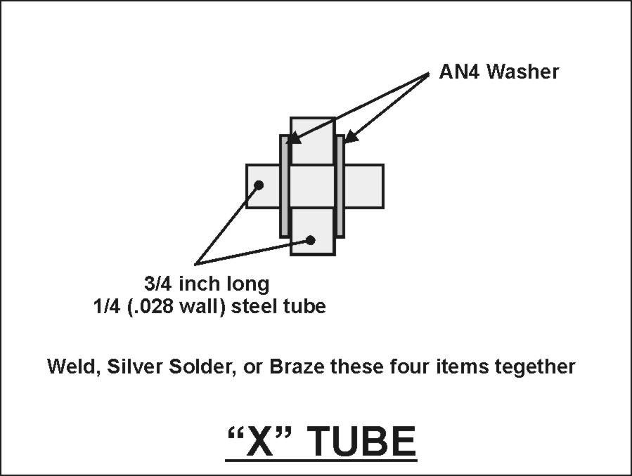
1 ft � x .028 wall Steel Tube (Cut off two pieces � long)
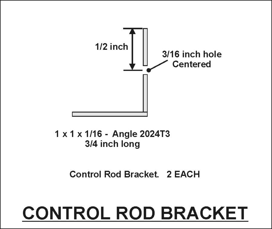
1 ft 1 x 1x 1/16 2024T3 Angle Aluminum (Cut off two pieces � inches long)
2 ea AN4 flat washer
6 ea AN3 flat washer
1 ea AN3-15A bolt
1 ea AN3 self locking nut
2 ea 4x32 self locking nut
2 ea Spring - 3 inches, 8 turns per inch, .375 OD - .275 ID (Purchase enough spring to make two extra springs)
2 ea 1 inch diameter stainless hose clamps
4 ea #6 x � inch sheet metal screws
7 in 4x32 threaded rod ( Purchase at Hobby Store)
5 in Nylon tube (Purchase at Hobby Store)
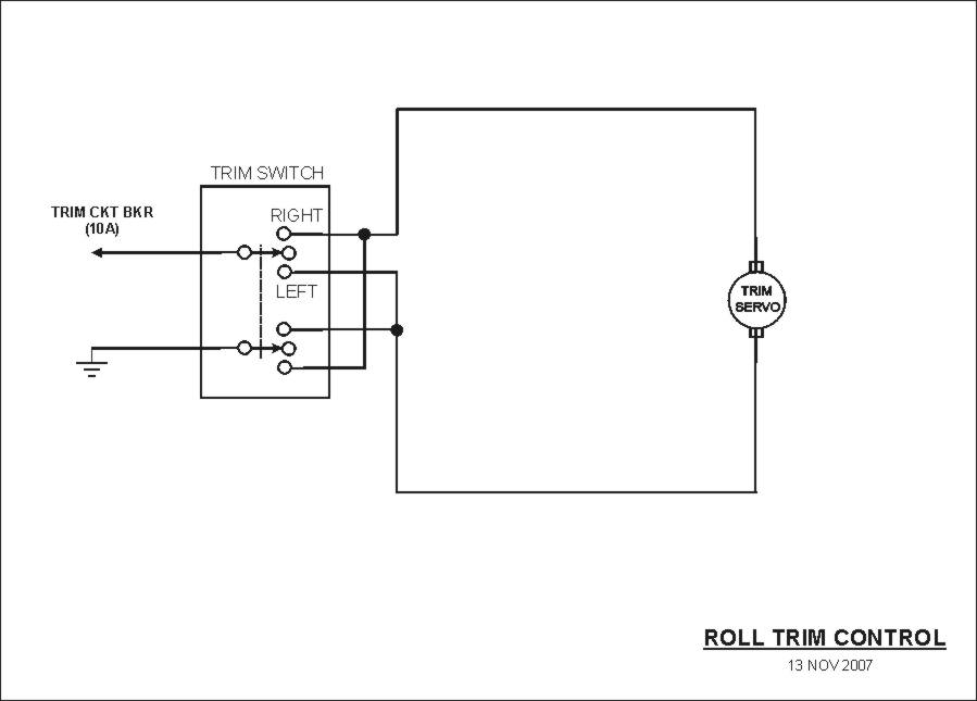
ELECTRICAL
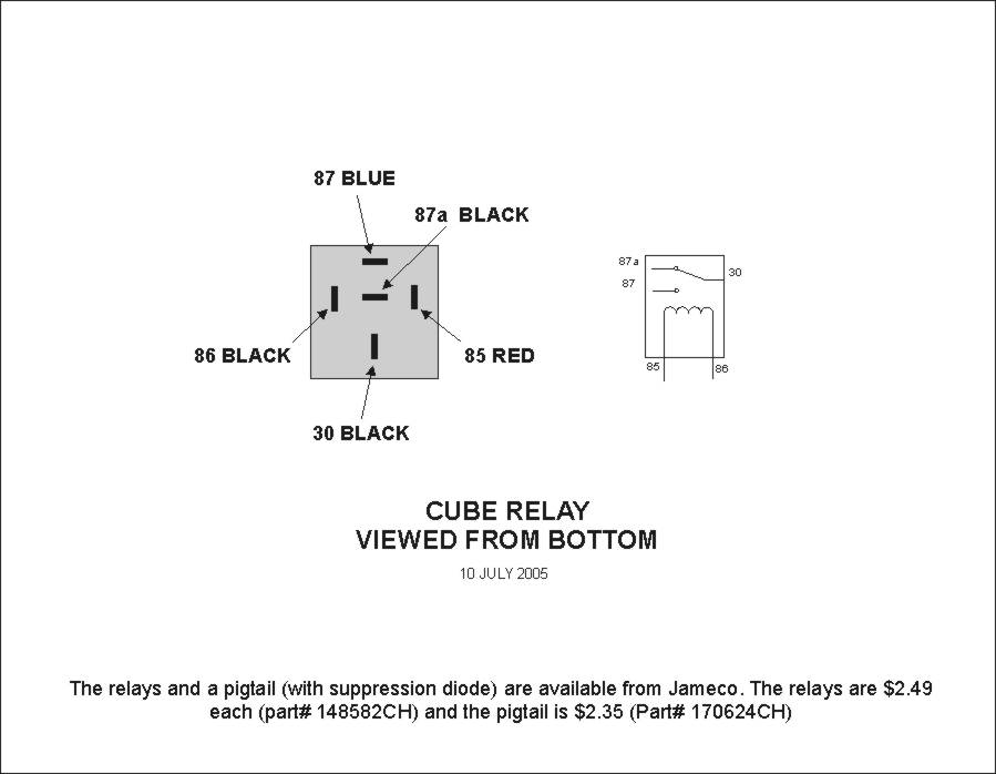
Follow the installation instructions that came with the Servo. Review the following drawings, There are two styles of connections, Direct to the Servo motor, and Via power relays.
Your choice will depend on the type of switch you use to control the servo. i.e. The Infinity Stick uses a "Coolie Hat" switch. These are two seperate momentary contact switches that cannot reverse the current flow for the servo motor, so we need to use relays.
If you use a Double Pole Double Throw switch, you'll be able to wire directly to the Servo moter as the switch is wired so it reverses the current flow.
You can buy just the servo (my recommendation) or a kit that includes a switch and a position indicator.
I bought just the servo and used my own switch.
My original installation, I used a small snap in rocker switch, Double Pole Double Throw (DPDT), three position, momentary contact, with center off.
 The switch was recessed into the left console, just below and aft of the Throttle assembly. If you had X-Ray vision (see photo), the switch was situated so it was just in front of the original pitch trim, and in between the two pitch trim cables.
This is a generic description of how I installed my switch, The size of the hole depends on the switch you use.
Try Mouser Electronics
Part Number = 629-GRS4023C13
Don�t cut any holes until you have the switch in hand.
In my example, the switch would snap into a hole � x � inch. The outer dimensions of the switch are 1 x � inch.
1) Locate the position of the switch on the side console. The switch will be oriented UP/DOWN, not forward back. I.e. Press the top of the switch = trims left, press the bottom of the switch = trims right.
2) Mark a rectangle, 1-1/4 tall by 1 inch wide, for the switch cutout, center it at the switch position.
3) Carefully cut the outer skin only following the outline from step 2.
4) Remove the small piece of outer skin, then clear away foam to the inner skin.
5) On the underside of the outer skin, trim away about � foam. This will be a flox corner that will form the recess that out switch will mount in.
6) Place a small bead of flox on the underside of the outer skin. Lay up three layers of BID into the recess and onto the flox.
7) When ready, knife trim the BID so its even with the outer skin.
8) When cured, sand the newly formed recess smooth, no sharp edges.
9) Center the cutout dimensions for the switch inside the recess. Cut out the recess.
10) When you route the wires to the switch, make sure they will not rub against the pitch trim cables.
11) Connect the wires to the switch, Check servo operation and direction.
12) Snap the switch into the recess.
ASSEMBLY
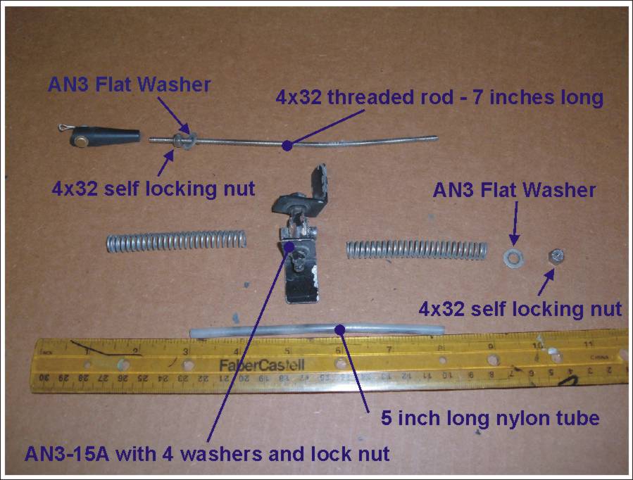
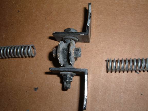
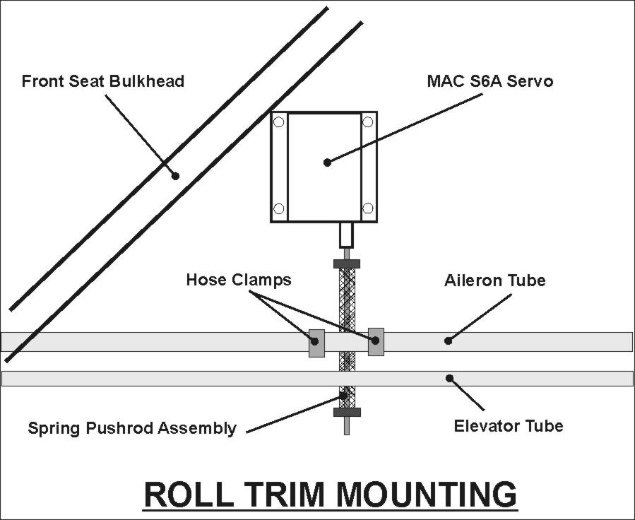
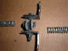
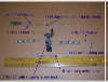 The following photo shows how Waiter�s Roll Trim system is assembled. Review the photos and drawings.
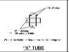
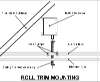
1) Review Figure 1, �X� TUBE. Weld the �X� tubes together. The AN4 flat washers MUST be welded into place.
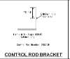
2) Review Figure 2, CONTROL ROD BRACKET. Drill a 3/16 hole in each of the brackets. Position the hole center, and � inch from the outer edge.
3) Review Figure 3. Assemble the �X� tubes, AN3-15A, AN3 flat washers, and Locking nut. Tighten the nut so the �X� tubes move freely around the Control Rod Brackets, No binding, and not to much play.
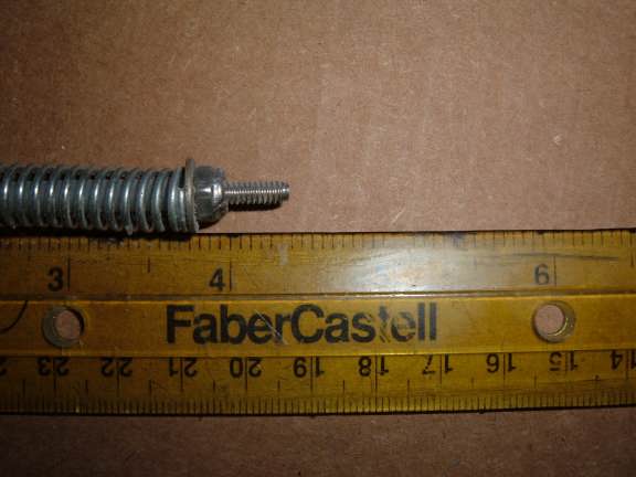
4) Cut the 4x32 threaded rod to 7 inches. Clean up the threads on each end.
5) Place a 4x32 nut on one end of the rod, thread to about � inch.
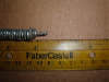
6) Cut the Nylon tube to 5 inches.
The Nylon tube must fit over the 4x32 threaded rod.
The Nylon tube must slide freely inside
7) Slide the tube over the Threaded Rod. It should fit against the Nut from step 5.
8) Slide one AN3 washer over the rod/tube. It should rest against the Nut from step 5.
9) Slide a spring over the rod/tube. It should rest against the washer from step 8.
10) Slide the �X� tube over the rod/tube. The spring should from step 9 should ride up on the outside of the �X� tube and rest against the AN4 washer that was welded to the �X� tube. ( Look at the photo in step 3)
11) Slide other spring over the rod/tube. It should rest on the other side of the �X� tube.
12) You�ll need to hold the springs compressed in the following steps.
13) Slide an AN3 washer over the rod/tube. It should slide up on the Nylon tube and rest against the spring that your holding compressed.
14) Install the other 4x32 locking nut on the end of the 4x32 threaded rod. You can hold the other end (fin step 5) with a pair of pliers. Tighten the 4x32 nut until it rests against the nylon tube.
15) Screw the spring rod assembly onto the 4x32 fitting located on the MAC servo, As far as it will go.
INSTALL WAITERS ROLL TRIM ON AIRCRAFT
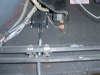
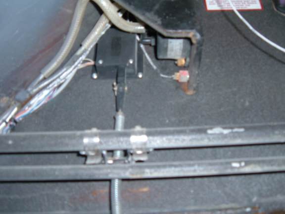
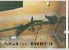
I located the Roll Trim Servo system in the rear seat, as far forward against the front seat bulkhead.
My servo is protected by the installation of a mini instrument panel in the rear seat. The following photo is taken looking UP from the floor of the rear seat. You can see the MAC Servo mounted just in front of the Airspeed indicator.
CAUTION - Its possible that a rear seat occupant could rest their knee against the servo and interfere with its operation. I would recommend a small fiberglass cover to protect the MAC servo from inadvertent knees.
INSTALLATION
1) Install the two Stainless clamp onto the Aileron Torque tube. Leave them loose.
2) Position the system in its approximate location. Slide one of the Stainless clamps over the forward Control Rod Bracket.
3) Slide the other Stainless clamp over the other Control Rod Bracket.
4) Position the Stainless clamps so that the heads are resting on the Control Rod brackets. This will place the heads between the Aileron Torque tube and the fuselage wall.
This positions the heads so that they will not be protruding out into the rear seat are where they could catch on rear seat occupants clothing.
5) Check the position of the MAC Servo. It should be as far forward as possible, BUT, not against the front seat bulkhead (Maybe � to � inch from the bulkhead).
6) Tighten the two hose clamps. (They�ll be readjust a little later, we are just checking clearance for the MAC Servo.
7) Hold the MAC Servo in position with your hand. Twist the Aileron Torque tube, It should move freely, there should be binding of the �X� tube as it slides up and down on the nylon tube.
8) When satisfied with the position, use 4 self tapping sheet metal screws and mount the MAC servo to the Fuselage.
9) Verify that there is no binding of the �X� tube (step 7)
ADJUSTMENTS
There are two adjustments that can be made to Waiters Roll Trim System;
a) CENTERING � This is the easiest, and can be done in minutes.
b) RANGE � This is the spring tension that�s applied to the torque tube. This is a little more difficult and may require removing the spring rod assembly.
The range can be made tighter (more spring tension) by removing the bottom 4x32 nut, sliding the nylon tube down a little, cutting off a small amount of the nylon tube (1/4 inch), sliding the nylon tube back up, then reinstalling the
CENTERING
The CENTERING adjustment must be performed prior to first flight. After flight testing, you may need to make small adjustment to get the center a little closer.
With fuel tanks loaded equally and the aircraft at your normal cruise speed, the MAC servo should be just about center.
1) Loosen the two Hose Clamps.
2) Using the �TRIM� switch, position the MAC servo so that its in its center position.
3) Hold the Stick full Left (turning left). Tighten the Stainless steel hose clamps.
4) TEST FOR FULL TRAVEL. You should be able to easily override Waiters Roll Trim System with the stick.
Send the trim to full left. Move the stick to full right. You can feel a little of the spring loading, but you should be able to move the stick, freely with no binding.
Now send the trim to full right. You should be able to move the stick full travel, with no sticking or binding.
RANGE
With the plane in a normal configuration and the CENTER adjusted properly, The trim should be able to adjust for about a 10 � 15 gallon difference between the strakes.
The RANGE adjustment is a little more difficult. We are going to add or subtract spring tension to get range.
ADDING TENSION � This can be done either by changing the springs (one more turn of the spring) or shortening the nylon tube by a small amount. (1/4 inch)
REMOVING TENSION � This can be done by changing springs (cut off one turn of the springs ) or lengthening the nylon tube (1/4 inch)
NOTE � Changing the length of the Nylon Tube may be the easiest to do.
CHANGING NYLON TUBE LENGTH
1) Review the assembly procedures from above.
2) Remove the bottom 4x32 nut.
The bottom washer and bottom spring will fall off.
3) You should be able to slide the old Nylon tube out.
4) If the Nylon tube is made longer, i.e. � inch, the top 4x32 nut must be moved up approx 1/8 inch (two turns).
If the Nylon tube will be shorter, i.e. � inch, the top 4x32 nut must be moved down approximate 1/8 inch (two turns)
You must move the top nut if you change Nylon Tube length, this will keep the spring assembly �X� Tube centered.
5) Slide the new tube over the 4x32 threaded rod. The Nylon tube must rest against the top nut, NOT the top AN3 washer. The AN3 washer must slide over the tube.
6) Reinstall the bottom spring, AN3 washer. Hold these compressed while you reinstall the bottom 4x32 nut.
7) Tighten the bottom nut so it just touches the Nylon Tube. Recheck the Nylon Tube is resting against the Top 4x32 nut, and not the AN3 washer.
8) Perform the TEST FOR TRAVEL as outlined above. NO BINDING.
CHANGING SPRINGS
Changing spring length will be easier if the rod spring assembly is removed.
1) Loosen the hose clamps and slide them off the Control Rod Brackets.
2) Remove the cotter pin and roll pin from the MAC Servo arm that the Spring/Rod assembly is screwed into.
3) Replace the springs in a manner similar to the initial assembly.
4) Reinstall the Rod Spring assemble onto the MAC Servo.
5) Reinstall the Hose clamps as described in the initial assembly directions.
Good Luck
Waiter
Waiters GPS Set Time program.
Waiters Flight Data Recorder.
Flight Data Recorder.
Recording aircraft flight data.
Aircraft Voice recorder.
Garmin GPS.
Garmin GPS Serial data Format.
Recording EFIS data.
Capture Serial data.
Convert Raw Data Files.
Free GPS Software.
Reading GPS data.
Reading Garmin GPS data.
Aircraft EFIS Flight Instruments.
Electronic Flight Instruments.
Aircraft Engine Monitor System.
Garmin G format.
Infinity landing gear LongEZ Plans Built Airplane.
Oil Heat system for Homebuilt airplane.
LongEZ Canard and main Wing.
Dynon instrument panel.
Custom Mouse cursors.
Garmin Serial Data Format.
Easy, Free Computer Time setting by GPS Receiver.
Custom mouse pointers.
Custom airplane mouse pointers.
LongEZ Nose gear doors.
Long-EZ main landing gear doors.
LongEZ grasscutter landing gear door.
Custom LongEZ mouse pointers.
Lycoming engine in LongEZ.
MT Propellor with 6 inch propellor extension.
EZNose Lift retractable nose gear for Long-EZ.
Rutan LongEZ is a plans built aircraft.
High speed homebuilt airplane.
Retractable landing gear for LongEZ.
Custom Airbus mouse cursor pointer.
Custom Velocity mouse cursor pointer.
NMEA 0183 Serial data Format.
Custom Cozy mouse cursor pointer.
Custom Aerocanard airplane mouse cursor pointer.
Custom E-Racer mouse cursor pointer.
Custom Canard airplane mouse cursor pointer.
Custom LongEZ mouse cursor pointer.
Set your Computer clock with this free GPS software.
Custom F15 mouse cursor pointer.
Custom A10 Warthog mouse cursor pointer.
LongEZ Hydraulic pump.
Retractable landing gear for a Long-EZ.
Custom F16 mouse cursor pointer.
Custom F14 mouse cursor pointer.
Custom Boeing 747 mouse cursor pointer.
Custom Boeing 767 mouse cursor pointer.
Custom Boeing 777 mouse cursor pointer.
Custom Boeing 737 mouse cursor pointer.
GPS Time Sync.
Custom Boeing 727 mouse cursor pointer.
Landing gear door rigging.
Custom Boeing 757 mouse cursor pointer.
Custom MD80 mouse cursor pointer.
Custom DC9 mouse cursor pointer.
Setting your computer to a GPS Time.
Custom RV mouse cursor pointer.
Downdraft cooling for LongEZ.
Speed brake installation.
Waiters Flight Data Recorder.
LongEZ Baggage pods installation instructions.
Waiters Custom Airplane mouse cursors.
Free GPS Time Sync Program.
LongEZ Intercom installation.
Major airframe overhaul of plans built EZ.
Weight and balance for a LongEZ.
Weight and Balance spreadsheet download for a Long-EZ.
LongEZ fuel system design.
How To remove the wings from a LongEZ.
How To remove the canard from a LongEZ.
Waiters GPS Time sync program runs on PC.
How To remove the engine from a LongEZ.
Long-EZ Downdraft cooling for a Lycoming O-320.
Long-EZ Wing Removal and installation instructions.
Waiters Retractable Landing Gear Controller.
Landing Light installation in LongEZ.
Install free EFIS software on your PC.
How to Put several longezs in one hangar.
How to install an Infinity Aerospace Retractable landing gear in a Long-EZ.
How to install DownDraft cooling on a Long-EZ.
GPS Time.
Setting you computer clock to GPS time.
How to set your Computer clock to GPS Time.
Using your GPS Receiver to set your computers clock.
Low cost GPS receiver used to syncronize Computer clock to GPS time.
Neat Canopy stay system for an EZ.
Cabin Heat using engine oil as source.
Waiters GPS Time, Syncronize your PCs internal clock with the GPS satellite.
Remote display of EFIS on a PC.
Cabin Oil Heater for a LongEZ.
LongEZ Landing Gear Door.
Rigging a LongEZ Landing Gear door.
Icom Radio in LongEZ.
How to Build a Manometer.
LongEZ Electrical system upgrades.
Grand Rapids EMS.
Custom Windows cursors.
Custom Windows mouse pointers.
LongEZ Cowling for downdraft cooling.
Record holding LongEZ flights.
Using a PLC for a retractable Landing Gear Controller in a LongEZ.
Syncronize your PCs clock to a GPS receiver.
Airspeed vs pressure lookup tables.
How to build a homebuilt airplane.
Video of LongEZ taking off.
Grasscutter landing gear door.
EZ Nose Lift installation.
Landing Gear status indicator.
Shareware software can set your PC clock vie a GPS receiver.
Landing Gear controller computer for LongEZ.
Landing gear doors.
Dynon EMS10 installed in instrument panel of a LongEZ.
Dynon EFIS D10A installed in instrument panel of a LongEZ.
Flight Data Recorder Software.
PlansBuilt LongEZ.
Video of High G turn in a Long EZ.
Strong Pitch Trim system installed in a LongEZ.
Strong Pitch Trim mounted on Left Side of Long-EZ.
Free software sets your PC clock with a GPS receiver.
Video of LongEZ Taking off.
Video of LongEZ Landing.
Video of LongEZ performing a high G turn.
Video of Infinity Landing gear being retracted into a LongEZ.
LongEZ Color White.
Painting your LongEZ.
White LongEZ.
Camoflage LongEZ.
Infinity Landing Gear for LongEZ.
Strong Pitch system.
|